RAF DataREVERSE-AIR-FLOW = 25% COOLER OPERATING TEMPERATURE
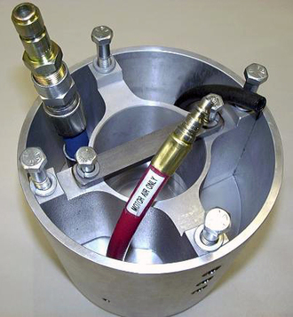
Our Reverse-Air-Flow design simply means that the atomizer motor cooling air flows in a reverse direction when cooling the OEM motor. As you may know, the conventional OEM air flow is designed so that the cooling air supply is plugged into the back of the motor with the heated air exiting the front of the motor where it heats up the critical resin passage areas of the atomizer housing. With RAF the cool air supply is plugged into a hose in the housing and enters the front of the motor (see red hose in photo). The heated exhaust air exits the rear of the motor, preventing heated motor air from contacting the critical resin passage areas of the atomizer housing and supplying cooler air to the front motor bearing. The result, as shown below is a cooler operating atomizer and front motor bearing, which often means longer run times.
|
This data is the result of extensive independent testing performed by the Natural Resource Research Institute, University of Minnesota, Duluth (www.nrri.umn.edu)
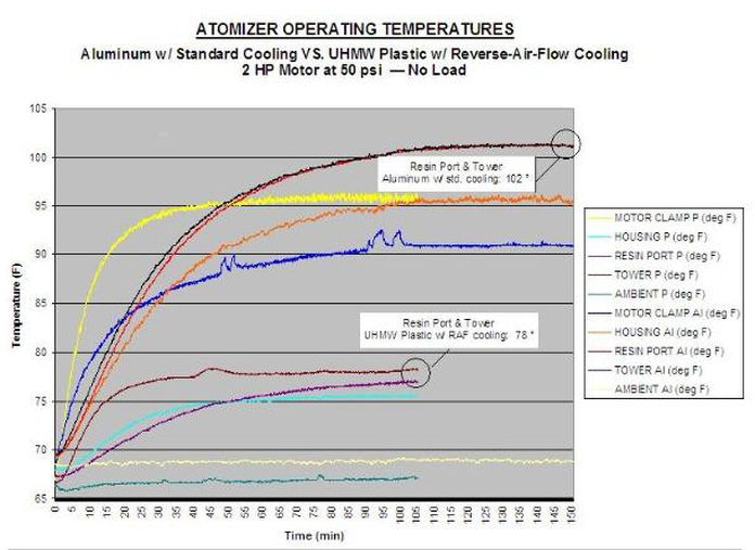
The tests compare a conventional aluminum atomizer housing set up with standard air flow for the motor cooling system to our Maximizer 4000 UHMW plastic atomizer housing with Reverse-Air-Flow cooling. The same 2 hp motor was used in both housings, running under no load with 50 psi air pressure. For Reverse-Air-Flow, the quick-coupler was simply removed from the rear of the motor converting the NPT hole in the rear bearing housing to an exhaust port.
Points of temperature probing were:
1. Motor Clamp (bar clamp at rear of motor)
2. Housing (mid point of outside surface of housing)
3. Resin Port (inside housing area behind resin plate)
4. Tower (small hub at center of housing surrounding the motor shaft)
The critical areas of Resin Port and Tower temperatures dropped 24° with RAF —a reduction of nearly 25% and the Housing temperature dropped 20°. While the rear of the motor shows a five degree increase in temperature with RAF, the front of the motor (near the resin port and tower) is operating cooler and the inlet air is also dispersed more evenly throughout the motor by entering six holes instead of one.


